12v Car Battery Charger Circuit
Diy pb charger duration.

12v car battery charger circuit. Here is a simple and easy to build circuit diagram of a 12v car battery charger. The article discusses 3 unique charger circuits. The two diodes forms a centre tapped full. This battery charger circuit can be used to charge one or more batteries with the total nominal voltage of 12 v meaning ten nicd battery or six 2 v lead acid.
It tapers off to 4a at 135v 3a at 140v 2a at 145v and 0a at 150v. The incorect usage is impossible. The circuit is pretty small and can be built in a housing network adapter. Sealed lead acid.
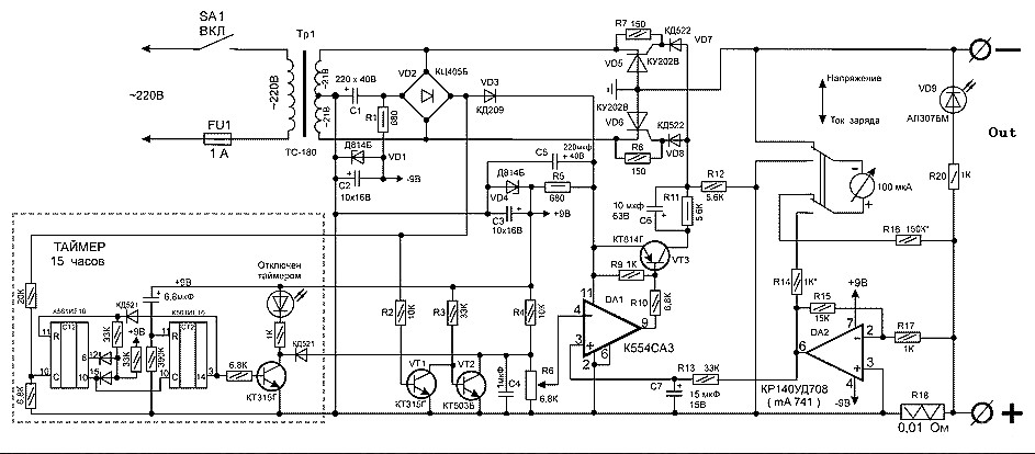
In this unit the full load current of the supply transformerrectifier section was 44a. The working of the circuit is as follows. Batteries with different potentials like 6v and 9v can also be charged by choosing appropriate components. This ac voltage is rectified and filtered to obtain an unregulated dc voltage used to charge the battery through a relay.
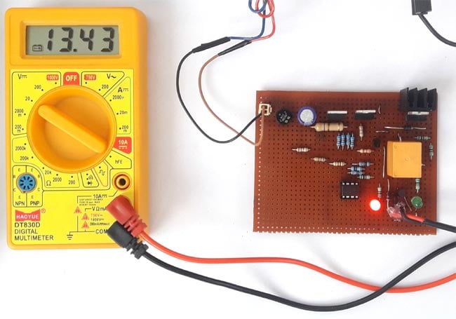
The circuit is nothing but a 12v dc power supply with an ammeter for monitoring the charging current. You might develop the one that fits your condition. This adjustment is done by the 10k preset and a multimeter connected with the output terminals that goes to battery. In this article we will build an easy 12v 100ah lead acid battery charger circuit which will give you 10a of current.
The battery is charged from a 230v 50hz ac mains supply. This 12v battery charger circuit with auto cut provides the automatic cut off facility when the battery get fully charged. It is crucial to understand exactly. It can be used to charge 12v batteries.
Posted thursday april 18 2013 unlike many units this battery charger continuously charges at maximum current tapering off only near full battery voltage. Before the use of this circuit you need to adjust the cut off voltage range for autocut. 12v battery charger circuit with auto cut off. This circuit can be used to charge all type of 12v rechargeable batteries including car batteries.
12v 100ah battery charger circuit. Last updated on july 26 2019 by admin leave a comment. Connecting the batteries with reverse polarity shortcircuit of the output terminals or power loss have no impact on the. Here is the circuit diagram of a simple and straight forward 12 v battery charger circuit with diagram.
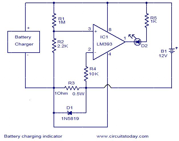
This is a simple car battery charger with indication. R1 1kohms d1 1n4001 t1 220v17v 4a transformer r2 12kohms d2 68v 05w zener ld1 green led r3 470 ohms tr1 47kohms trimmer ld2 red led r4 read more. How to charge high current lead acid batteries. An automatic battery charger circuit using scr is implemented in this project.
12 volt car battery charger circuit schematic. Car battery charger circuit working principle.


